EDS® Thermal Simulation
Modelling Cause & Effect
Computer simulation can be used to establish benefits or limitations in advance of changes to design proposals; or changes to the existing built environment. The calculation methods that are typically adopted include:
- Steady State Calculations- Dynamic Thermal Simulation
- Computational Fluid Dynamics (CFD)
Steady State (2D) Calculations
Routine Early Calculations Based On Broad Assumptions
 During the early design stages of a project engineers may use ‘steady-state’ calculations to determine building heating and cooling loads. Steady-state calculations are based upon known criterion, such as outside temperatures and internal requirements, and examine only one scenario at a given time.
For example, the engineer looking to establish heating demands may assume an outside temperature of 0oC and inside requirement of 22oC. Applying routine internal heat gain and material heat loss assumptions, they may then calculate the additional heat required to achieve comfort conditions for that particular scenario.
In a separate calculation to determine cooling requirements the engineer may assume an outside temperature of 25oC and wish to maintain the inside at 22oC. Again, applying routine internal and solar heat gain assumptions they may then calculate additional cooling requirements.
Steady State Limitations
The steady state calculation method ignores the transient nature of winds, solar gains, and shading related to physical obstructions.
This method does not consider the ability of building materials to store heat gains, or to the efficiency of the night cooling schedule.
Variable occupancy and window control strategies are also neglected by this method.
Outside temperatures are not limited to 0oC for six months and 25oC for the other six months of the year. Steady state calculations tend to overstate system requirement and contribute to the construction/operating costs and inefficiencies brought about by oversized equipment. A calculation method that considers actual weather conditions for each hour of every day, Dynamic Thermal Analysis, provides more accurate results.
Dynamic Thermal Simulation & EDS® Energy Modelling
Introducing Time, Operations, Airflow, Structural Thermal Capacity, Shading, and Weather
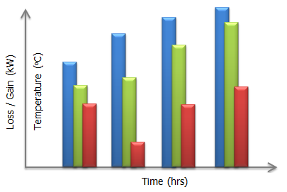
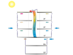
More accurate than Steady-State calculations, 'Dynamic Thermal' & 'Bulk Airflow' analyses consider time as a calculation parameter. A three dimensional computer model, including surrounding obstructions, is used to represent the working environment. The model is correctly orientated and a local weather file is attached (actual recorded weather data); the model is effectively located on-site. Occupancy schedules are also considered, as are materials and specific task-related heat gains.
 Surface Temperatures
 - Internal Space Temperatures (Dry Resultant, Mean Radiant, Dry Bulb, Wet Bulb)
- Dew-Point Temperatures (Condensation Analysis)
- Heat Loss (Fabric, Infiltration)
- Heat Gain (Casual, Solar)
- Heating Plant Loads
- Cooling Plant Load
- Free-Cooling offsets
- Relative Humidity
- De/Humidification Plant Load
- Occupancy Comfort Prediction
- Natural Ventilation Viability
- Air Quality (CO2 Concentrations)
Occupancy figures appear as heat gains and CO2 emitters in the overall calculations. Thermal capacities and free-cooling effects are considered in the calculation process. As such, this yields more accurate results over steady-state calculations.
 Further, the study examines the bulk flow, and velocity, of air within and around each zone in the building.
A bulk airflow study can be used to examine the overall airflow distribution and effectiveness of Heating and Natural Ventilation systems. The study also considers control strategies for valve & window openings and offers input into the Building Management System (BMS) control strategy. Proportional control of opening windows and louvres can be examined; temperature AND/OR CO2 setpoints are simulated.
Computational Fluid Dynamics (CFD)
Advanced Temperature & Airflow Calculations Producing A Graphical Output
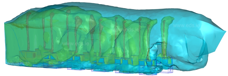
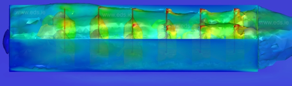
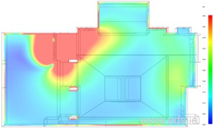
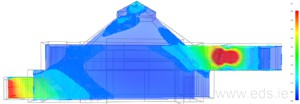
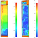 CFD is used to model physical fluid flows and heat transfer. An internal CFD analysis provides information on the distribution of fluid velocity, pressure and temperature (and several other calculated parameters) throughout the inside of building spaces.
Proposed changes to the working environment can be reflected in a 3D model to yield “cause & effect” scenarios before procurement & committing to works on-site. Cost/benefit and value engineering analyses can then be graphically represented.
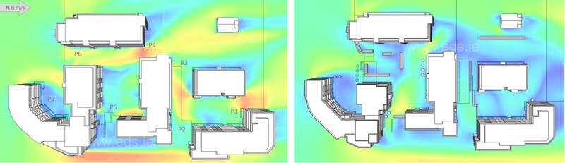
CFD examines a situation at an exact moment in time. Typically, the results yielded in the Dynamic Thermal model indicate a time/case of interest. In the as-built scenario the ‘Boundary Conditions’ for the CFD study can come from measured readings of air velocities, air temperatures and surface temperatures.
A combination of a Digital Anemometer & IR Thermometer or Thermal Imaging equipment are the most accurate instruments to determine boundary conditions. These are then applied to the model. Airflow, pressure, and heat distribution can then be displayed on the same image.
EDS® has used Dynamic Thermal Modelling and CFD to determine:
- The throw of air into an atrium or annexed space.
- Optimisation of mechanical services & control systems.
- The existence of draughts.
- The implications of fitting curtains to reduce/eliminate down-draughts near windows.
- The implications of introducing partitions.
- The implications of fitting auxiliary heaters.
- Smoke dispersion in fire scenarios.
- The optimal location of sensors.
- The implications of changing heating / ventilation schedules.
- Determine optimal time for systems to be ramped down.
- Determine optimal (real) demand from LPHW heating system.
- The optimal pulse duration and opening areas for windows in the ventilation schedule.
- Heat loss and insulation parameters.
- Determine the effectiveness of existing or proposed insulation and locations where it may be required.
- Predicted Mean Vote (PMV) & Predicted Percent Dissatisfied (PPD).
- Operative (comfort) & Draft Temperature.
- Air Diffusion Performance/Quality Index.
- Contaminant Removal Effectiveness (CRE).
EDS® CFD Facilities
EDS® provides RANS (Reynolds-averaged Navier–Stokes), DES (Detached Eddy Simulation) & LES (Large Eddy Simulation) CFD Services. These services have been applied to schools, offices, libraries, public buildings, retail units, restaurants, and clean rooms. EDS® also provides CFD services for individual non-building-related components and projects, such as energy generating devices and even conceptual car designs.

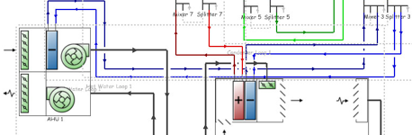
Heating Ventilation & Air Conditioning
Analyse & Optimise System Performance
Full air & water side HVAC systems modelling. Each emitter/diffuser on the schematic is assigned to a zone in the model. The results will reflect and compare any changes proposed to the original design. This is particularly useful in sizing additional HVAC elements and optimising system schedules & performance.
Contact Ciaran Flynn or Dr. Niall O'Sullivan for more information.
EDS® Projects |
|
|
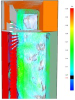
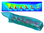
Data Centre Power Generation
Thermal and airflow simulation of 24MW power generation enclosur. Passive Design • Thermal Simulation • Design Validation • Performance Analysis • CFD |

|
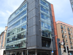
Facade Design, Dublin
Facade/shading design & material selection. Thermal Simulation • Design Validation • CFD |
|
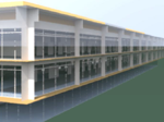
Open Plan Office Development (HVAC)
Thermal Analysis and HVAC design of commercial offices. Thermal Simulation • CFD |